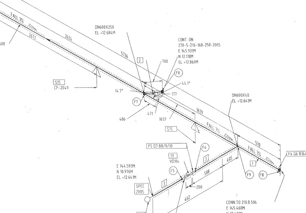

The process equipment and piping have priority over the piping arrangement. The vertical lengths of the pipe can be calculated by using elevations, while the horizontal lengths are calculated by using north-south and east-west coordinates.

The pipe lengths are determined by calculations using coordinates and elevations.
Pipe diameter contents and identification number. What are the requirements for a piping drawing? By the help of these drawings and also with the project installation specifications would provide good guidelines to complete the piping system. There are different types of piping diagrams and they are process flow diagrams, piping and instrumentation diagram, orthographic pipe drawing, piping isometrics, and block flow diagrams. Piping diagrams are designed in a way that will be understandable for non-technical personnel. The drawings would help to speed up the fabrication and erection work at the site. These drawings are schematic representations and they would define functional relationships in a piping system. Moreover an isometric is not overcrowded with other information, useless for piping and it is easy to visualize.The main purpose of a piping drawing is to communicate the information in a simple way. Isometric drawings are easier to be used for stress analysis of the piping, fabrication and construction, compared to other orthographic drawings, since they carry all the necessary information for these tasks. Upon completion and approval of the piping isometrics, they are used for fabrication and then construction of the piping system. For complex piping systems, individual pipe runs are represented on separate isometric drawings. A table gives the number and detailed description of each type of fittings represented on the drawing. In addition, all the fittings including, valves, flanges, elbows etc. 
The operating and design process conditions (pressure and temperature) for the pipe run may also be reported on the isometric. This line number is indicative of the fluid service, piping class and material, insulation etc. The line numbers for lines pipe runs represented on the drawing is clearly indicated. Straight lengths of all the pipe runs on the drawing are reported as clearly as possible. Isometric drawings carry a graphical representation of the 3 dimensional piping system being represented.


 0 kommentar(er)
